This calculator produces a table of carriage and cross slide movements. With this table an operator can use a lathe equipped with the parting tool of choice to mimic a radius or parting tool cutting an arbitrarily curved groove in the side of a part. The calculator will produce this table using the chosen step size for either roughing out a groove or for producing a groove that requires minimal filing.
There are three ways to find the desired Bézier curve, that I am aware of. I used a French curve stencil to find the cut for the Picture holders. This curve was held against the screen while dragging around the control points to get a good fit using the site, Bézier curve tutorial. A second way is to use the Grapher application on a Mac. A saved Bézier curve graph can be modified by altering the four control points. The third way is using a saved file called Bezier Curves at Learn Maple. Again the control points have to modified to change the curve.
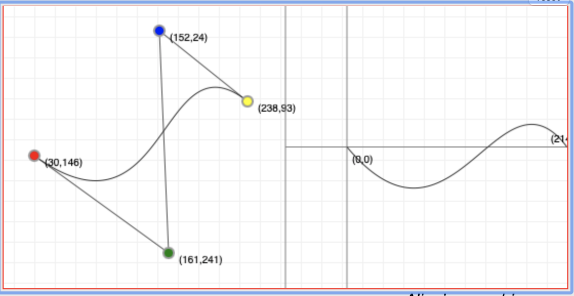
As an example using the Bézier curve tutorial cited above, drag the colored dots or handles until you get the desired curve shape. The screen capture below shows the Bézier curve after dragging the handles around a bit. The normalized curve on the right in the screen capture shows the actual curve to be cut into a part on the lathe. Transfer the four sets of control points to the input form below to get the desired cutting instructions.
Need to log in to Learn Maple to use the web browser based math program and open the saved file. Google Chrome is the preferred browser for this application. Safari is prohibitively slow.
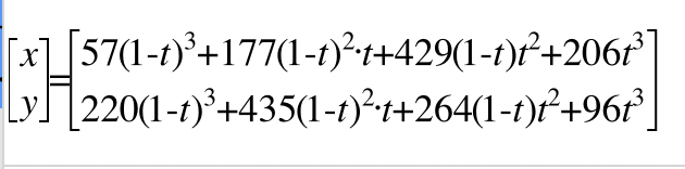
The coefficients in the two equations use the default control points discussed below. The two central coefficients in each equation do not use the control points directly, but add factors. So 177 = 59 + 118, 429 = 143 + 286, 435 = 145 + 290, & 264 = 88 + 176. The same (red) factors need to be added to any control points used for the central coefficients.
The program needs four parameters to produce the table of cuts: the four control points of the cubic Bézier curve that is the profile of the desired groove (e.g., (57,220),(59,145),(143,88),(206,96)), the width of the cut, the depth of the cut, and the step size (e.g., 0.010). Both should be entered in decimal form. (Entering fractions will produce an error of some type, dependent on your browser.) The program assumes that the stock to be cut is more than twice the groove radius in diameter. (Or you will be mimicking a cutoff tool!) The default precision is three decimals, but this can be changed as desired. The next optional parameter that can be modified is the filing "buffer". It defaults to 0.003". Using the formulas precisely will take the corner of the cutter right up to the curve. Any movement past this point will result in cutting too deep. Since filing is required to remove the shoulders, a little extra can be built in via the buffer to avoid cutting too deep.
The picture shows a large and inconsistent filing buffer.
Sampling Density, the last optional parameter, is a quirk of the algorithm used. Instead of solving the two parametric equations for x and y, which is extremely complex, the function is sampled. The total range of the function is split into Sampling Density parts. The numbers generated for each of these points is used as a lookup table when looking for a depth of cut that corresponds to a given x‑coordinate. As an example, if the curve is to span one inch, then the default Sampling Density of 500 gives a depth of cut value every 0.002". This should be sufficient coverage for a 0.010" wide cut. If the width of cut drops or the size of the curve grows, 500 may not be sufficient and should be increased.
To use the chart the following procedure is recommended. Any long stretches of minimal cross slide advancement should all be cut at once in the standard fashion to save time. After this the carriage is moved one step to the right and the cross slide is advanced according to the value in the table. When the 'stepped' curve is complete file as needed to produce the 3‑dimensional Bézier curve of your dreams!
The x's and y's listed in the table may be of value for a lathe equipped with DROs on both axes.
The challenge faced when implementing this is finding y from x. Finding the roots of these cubic equations is non-trivial. Consequently, a different path was used. A table of x values will be generated for a set number of t values in the range 0…1. A similar table of y values will be generated. A lookup algorithm will find the closest x‑value in the table and use the corresponding t‑value to find the associated y‑value in the y table.
This program only works for "simple" Bézier curves. That is, there is only one y‑value for each x‑value. That is you can't use this program for cuts requiring a cutting tool like a boring bar.
I found this code online under array functions: findLastIndex. It returns the index of the last element for which the provided function returns a truthy value. It uses Array.prototype.map() to map each element to an array with its index and value. Use Array.prototype.filter() to remove elements for which the fxn returns falsy values, Array.prototype.pop() to get the last one. -1 is the default value when not found. It will be used for the look up function.
const findLastIndex = (arr, fn) =>
(arr
.map((val, i) = [i, val])
.filter(([i, val]) = fn(val, i, arr))
.pop() || [-1])[0];
Examples:
findLastIndex([1, 2, 3, 4], n => n % 2 === 1); // 2 (index of the value 3)
findLastIndex([1, 2, 3, 4], n => n === 5); // -1 (default value when not found)
It was a struggle getting the code to work, when starting from a simple conversion of the round curve cutting tool. After putting some effort into planning the best approach to realizing this tool all went well.
The following assumptions are critical for utilizing this tool. You must start with a Bézier curve. The Bézier curve must be oriented as if it is on the part held in the lathe. There is a one-to-one correspondence between x- and y‑coordinates, e.g. the curve does not turn back toward its starting point. The output is formatted to assist cutting from the right end of the curve to the left. The maximum depth and width of the cut are known. The tool is not set up for face cuts, but the output could easily be adapted for a face cut.
The following steps are followed by the program.
Reload this HTML page between calculations, if you don't want successive calculations appended.